Laser Project - Configuration
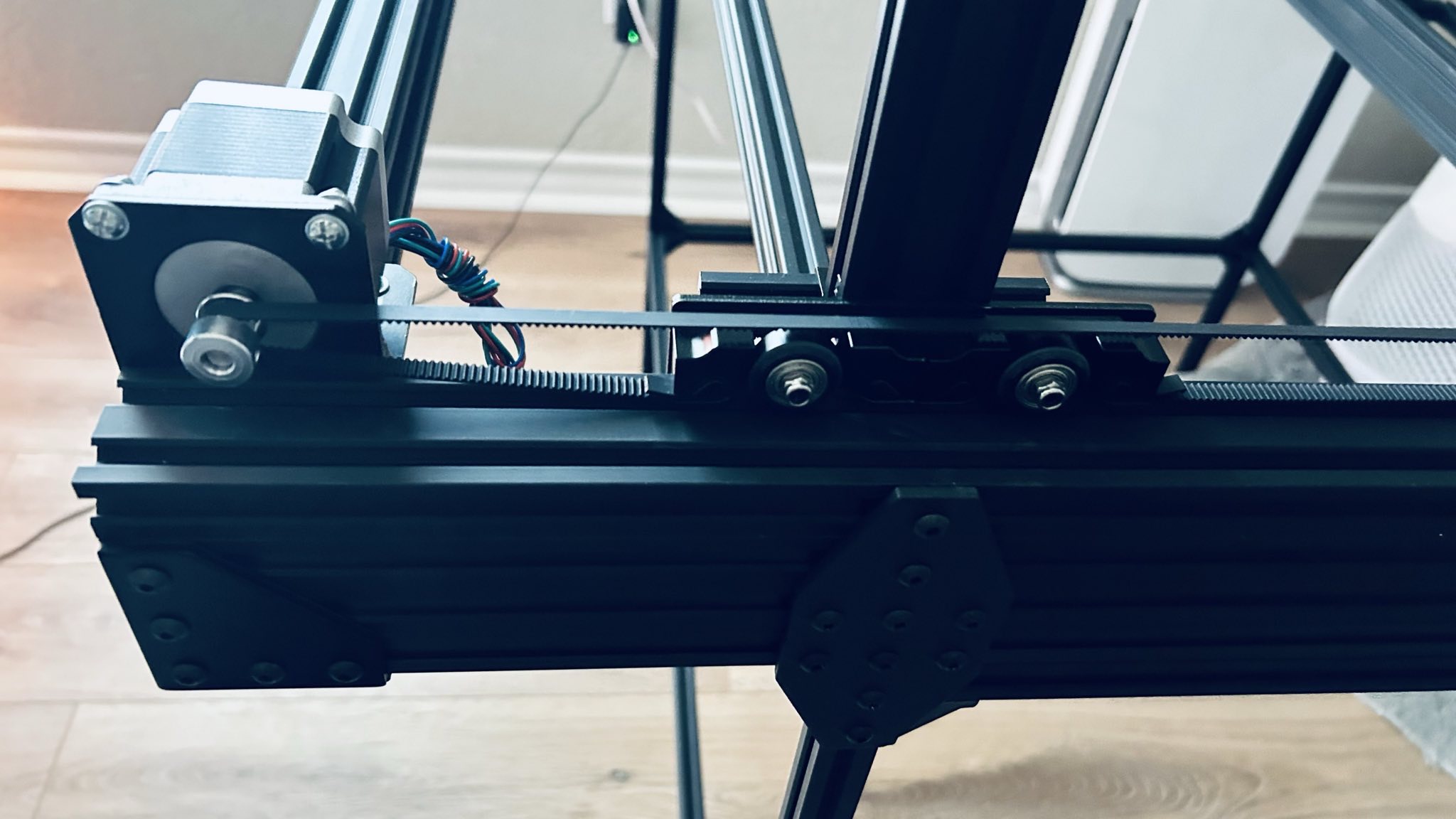
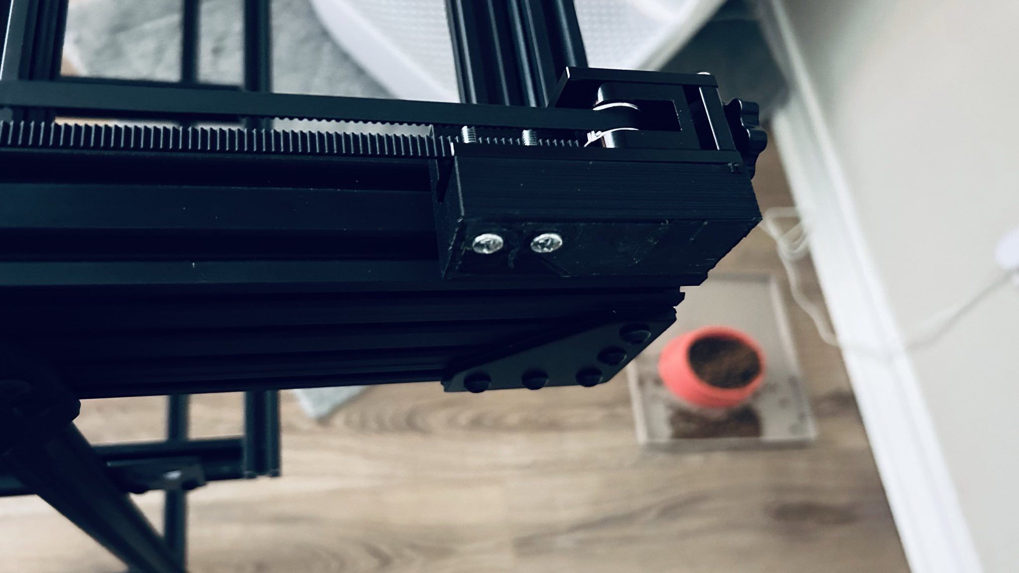
The Laser Project is a custom-built unit powered with the BIGTREETECH Rodent and a Laser Tree K30. This project has been designed and built from the ground up as a project for learning about cartesian-based CNC operations (and fueled with a passion for high-powered laser cutting!).
Parts, models, & components: coming soon.
Configuration:
Based on the design of this project, below is the configuration used for FluidNC. Because the laser design was only a 2-axis design, the z-axis configuration model has been removed and motor1 in the y axis configuration was added (with the pin settings from z). Furthermore, there has been a lot of ambiguity on the proper entries to use for FluidNC regarding the Rodent board. The overall consensus here was to utilize the guidance from BigTreeTech’s FluidNC Page and BigTreeTech’s GitHub.
The most important part of this section is utilizing the proper pins for each entry module. Based on the FluidNC’s guide, the following pins are the correct entries for each motor:
| PIN | DRIVE |
|---|---|
| I2SO.0 | X DISABLE |
| I2SO.1 | X DIRECTION |
| I2SO.2 | X STEP |
| I2SO.3 | LED R |
| I2SO.4 | Y DIRECTION |
| I2SO.5 | Y STEP |
| I2SO.6 | NOT USED |
| I2SO.7 | Y ENABLE |
| I2SO.8 | Z DISABLE |
| I2SO.9 | Z DIRECTION |
| I2SO.10 | Z STEP |
| I2SO.11 | LED B |
| I2SO.12 | A DIRECTION |
| I2SO.13 | A STEP |
| I2SO.14 | LED G |
| I2SO.15 | A DISABLE |
Here is the original rodent.yaml file that was included on the BTT Rodent board. This configuration was part of the FluidNC 3.0.8 NoGit version. During this process, the Rodent firmware (FluidNC) was updated to 3.8.2.
According to FluidNC’s wiki, the BTT Rodent has one small quirk that will cause the TMC drivers to not function properly; that is, if you only have 3 motors…
The spi_index value in the config file indicates which driver you are configuring. They are numbered 1 through 4, from left to right. FluidNC needs to know that there are 4 motor drivers in the daisy chain. If you are using less than 4, one of the drivers you need to use is number 4.
This led to two initial options, but ultimately, the best solution was to move the Y2 motor cable from the Z header to the Y header and reconfigure motor1 to use the A pins in the configuration.
Here is the configuration file used to get motion working:
board: BTT Rodent V1.0
name: BTT CNC
meta: (04.12.2024) by BTT

kinematics:
  Cartesian:

stepping:
  engine: I2S_STATIC
  idle_ms: 255
  pulse_us: 4
  dir_delay_us: 1
  disable_delay_us: 0

axes:
  shared_stepper_disable_pin: NO_PIN
  x:
    steps_per_mm: 80.000
    max_rate_mm_per_min: 5000.000
    acceleration_mm_per_sec2: 100.000
    max_travel_mm: 800.000
    soft_limits: false
    homing:
      cycle: 1
      positive_direction: false
      mpos_mm: 150.000
      feed_mm_per_min: 100.000
      seek_mm_per_min: 200.000
      settle_ms: 500
      seek_scaler: 1.100
      feed_scaler: 1.100

    motor0:
      limit_neg_pin: NO_PIN
      limit_pos_pin: gpio.35
      limit_all_pin: NO_PIN
      hard_limits: false
      pulloff_mm: 1.000
      tmc_5160:
        step_pin: I2SO.2
        direction_pin: I2SO.1:low
        disable_pin: I2SO.0
        cs_pin: gpio.5
        spi_index: 1
        r_sense_ohms: 0.075
        run_amps: 1.000
        hold_amps: 0.500
        microsteps: 16
        toff_disable: 0
        toff_stealthchop: 5
        use_enable: false
        run_mode: CoolStep
        homing_mode: CoolStep
        stallguard: 16
        stallguard_debug: false
        toff_coolstep: 3
        tpfd: 4

  y:
    steps_per_mm: 80.000
    max_rate_mm_per_min: 5000.000
    acceleration_mm_per_sec2: 100.000
    max_travel_mm: 800.000
    soft_limits: false
    homing:
      cycle: 1
      positive_direction: true
      mpos_mm: 150.000
      feed_mm_per_min: 100.000
      seek_mm_per_min: 200.000
      settle_ms: 500
      seek_scaler: 1.100
      feed_scaler: 1.100

    motor0:
      limit_neg_pin: NO_PIN
      limit_pos_pin: gpio.34
      limit_all_pin: NO_PIN
      hard_limits: false
      pulloff_mm: 1.000
      tmc_5160:
        step_pin: I2SO.5
        direction_pin: I2SO.4:low
        disable_pin: I2SO.7
        cs_pin: NO_PIN
        spi_index: 2
        r_sense_ohms: 0.075
        run_amps: 1.000
        hold_amps: 0.500
        microsteps: 16
        toff_disable: 0
        toff_stealthchop: 5
        use_enable: false
        run_mode: CoolStep
        homing_mode: CoolStep
        stallguard: 16
        stallguard_debug: false
        toff_coolstep: 3
        tpfd: 4

    motor1:
      limit_neg_pin: NO_PIN
      limit_pos_pin: gpio.33:pu
      limit_all_pin: NO_PIN
      hard_limits: false
      pulloff_mm: 1.000
      tmc_5160:
        step_pin: I2SO.13
        direction_pin: I2SO.12
        disable_pin: I2SO.15
        cs_pin: NO_PIN
        spi_index: 4
        r_sense_ohms: 0.075
        run_amps: 1.000
        hold_amps: 0.500
        microsteps: 16
        toff_disable: 0
        toff_stealthchop: 5
        use_enable: false
        run_mode: CoolStep
        homing_mode: CoolStep
        stallguard: 16
        stallguard_debug: false
        toff_coolstep: 3
        tpfd: 4

i2so:
  bck_pin: gpio.22
  data_pin: gpio.21
  ws_pin: gpio.17

spi:
  miso_pin: gpio.19
  mosi_pin: gpio.23
  sck_pin: gpio.18

sdcard:
  cs_pin: gpio.0
  card_detect_pin: NO_PIN
  frequency_hz: 8000000

# Begin Huanyang
uart1:
  txd_pin: gpio.15
  rxd_pin: gpio.16
  rts_pin: gpio.14
  baud: 9600
  mode: 8N1

Huanyang:
  uart_num: 1
  modbus_id: 1
  tool_num: 0
  speed_map: 0=0% 0=25% 6000=25% 24000=100%
  off_on_alarm: false

# PWM:
#   pwm_hz: 5000
#   output_pin: gpio.13
#   enable_pin: gpio.25
#   direction_pin: gpio.15
#   disable_with_s0: false
#   s0_with_disable: false
#   spinup_ms: 0
#   spindown_ms: 0
#   tool_num: 0
#   speed_map: 0=0% 10000=100%
#   off_on_alarm: false

i2c0:
   sda_pin: gpio.27
   scl_pin: gpio.26

status_outputs:
  report_interval_ms: 500
  idle_pin: I2SO.11:low
  run_pin: I2SO.14:low
  alarm_pin: I2SO.3:low